Astronomy: equipment 7

Updated: May 2024

Click here to better view this site

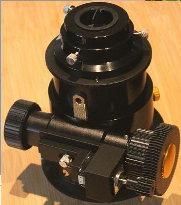
The GSO Ritchey-Chretien 16" Optical Tube Assembly (OTA) has been troublesome to me and to many others on the web. Mainly, the collimation doesn't hold over temperature changes and where its pointing - the former due to differential expansion coefficients of the aluminum saddle bars and the truss carbon fibre rods, and latter from the stresses emparted to the truss from the flexing of the saddle bars. Stars went from circular at 2.5"/sec FWHM to 45"/sec heavily distorted under -5C in winter as compared to summer when it was collimated. A further source, albeit less so, is the stock mono-rail focuser that can't hold the optical axis with a 5kg imaging train. A mono-rail focuser is great, so long as the bearing is scaled to the imaging payload.

I had worsened these effects by:

1) mounting the OTA in a fork mount that is difficult to align the declination bearings imparting stresses to the OTA with declination
2) making my own solid saddle bars (Losmandy style dove tail saddle mounts are not easy to use on a fork)

With temperatures ranging from -30C to +30C in Ontario, I tested the theory of differential expansion by milling out my solid saddle bars and the useful range had moved down to -15C. To both solve this and the fork mount declination axial misalignment, I was going to build a large frame to hold the RC16 only from its middle truss plate, but that would have been a challenging exercise. Finally I chose to go to my original design of an offset single arm mount, holding the OTA only from one side. I was going to cut off one of the fork arms but reasoned that if I kept it, it would handle much of the balancing weight required and also allow going back to a fork mount if that came to be.

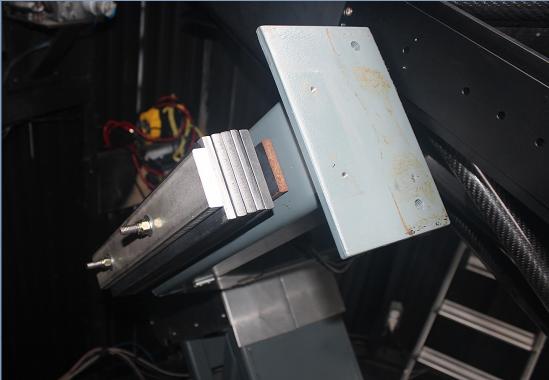
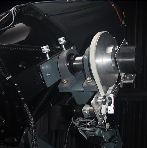
I therefore took the OTA off, extended the western declination bearing plate, installed both bearings on it, which gave a very solid, stable and zero backlash support. I also tossed my milled out saddle bars and went back to the GSO dove saddle bars. I also had to move the encoder to that side of the scope. Despite keeping the eastern fork arm, I had to add 25 lbs of counter weight. I surmise this is probably the only fork mount ever to have graced the earth that only has its OTA connected on one arm!

There hasn't been suitable skies to test this configuration out, but I observed (with no surprise) that the GSO saddle bar twists from the 50kg OTA, which surely applies stress on the truss plates. Costlier RC scopes use sturdy saddle bars and a flexing lateral plate between the bar and OTA to handle the differential expansion but otherwise hold solidly in the other two axes. I contemplated doing so, but there is no margin to doing so unless I cut the free fork arm off.
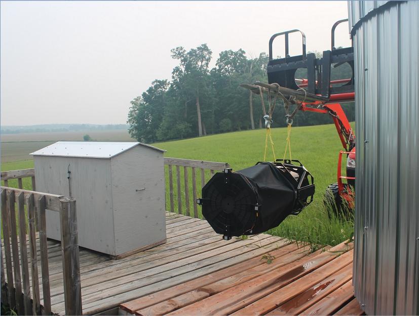
The OTA had to be removed from the observatory to work on the mount. It's quite a nerve racking experience, both when using the hoist to remove the OTA from the mount, and tractor to bring it to the shop 150m away. I plan on changing the hoist so that its on its own removable and adjustable gantry that will ride on the turret's upper slit rails, thereby allowing it to be used for both observatories.
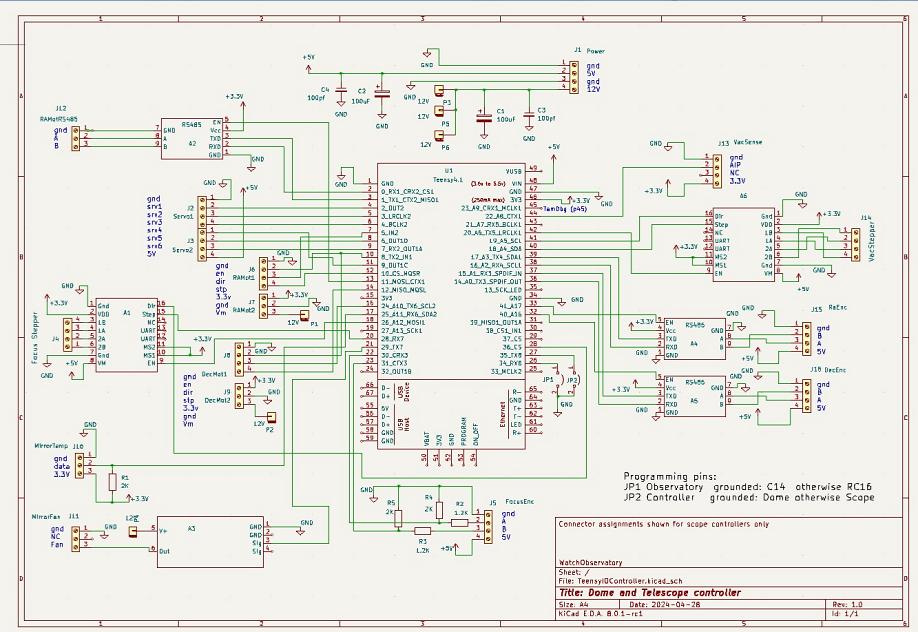
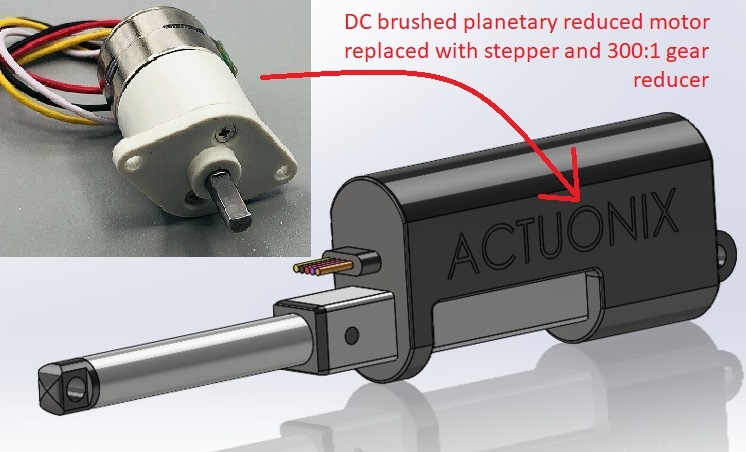
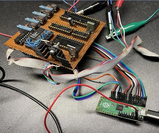
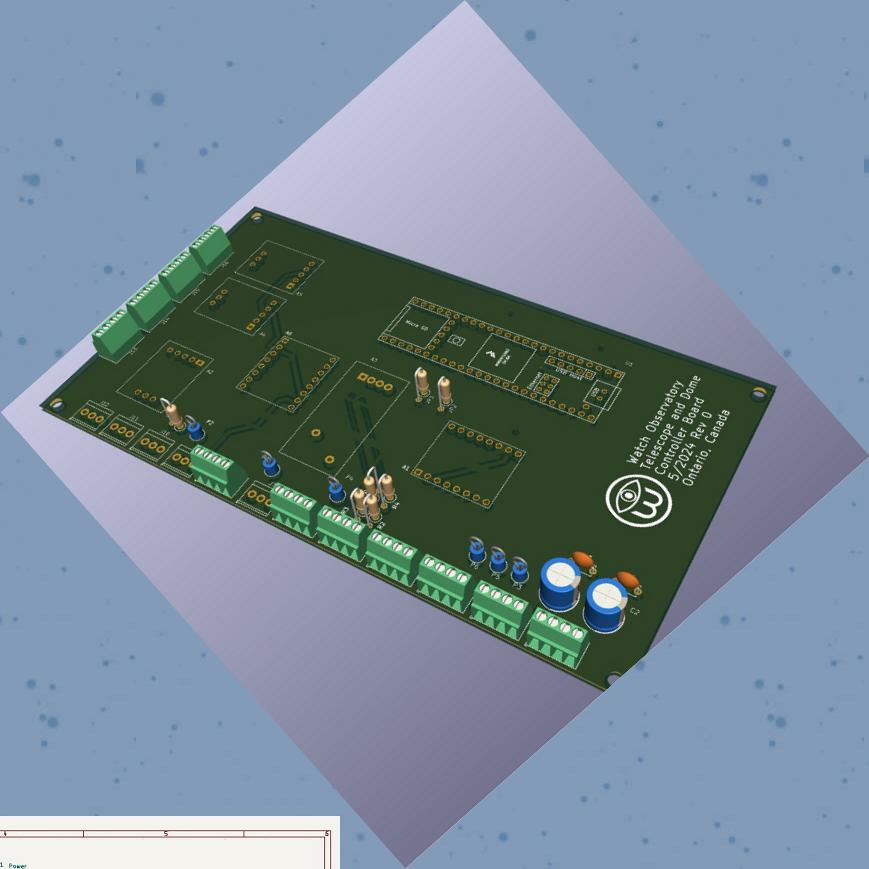
Another improvement was to change out the brushed DC planetary 250:1 geared motor of the Actuonix P16 linear actuator with a 300:1 geared stepper motor, as despite the gearing and PWM control, it was troublesome to control the focus precisely for FocusMax v5 to reach its full potential. Fortunately the eBay 5$ geared stepper had the same shaft keying so it fit right in. To control the stepper, I reused the same design I did for the RA drives of both scopes, that is an RPi Pico, Pololu STSPIN820 stepper driver and Python interfaced by VCP over USB. It improved the controllability ten fold - problem solved.
And then Month laters... on the R/C telescope fb group they spoke of a TS Optics 3" rack and pinion focuser for the GSO 16" at 1/3rd the cost of the FeatherTouch such that even making my own with a monorail wasn't worth it. I bought it and added 3D printed parts and a Nema 8 stepper. The focus position feedback will remain the linear encoder currently on the scope.

Also, tired of USB and Phidgets and to replace them all, I designed a generic controller board around the Teensy 4.1. Two per observatories, one on the scope, the other for the dome. I put one together with wires and solder, followed by having PCBs made online - supports steppers, quad encoders, absolute serial encoders, 1 wire temperature gauges, and so much more, easily. Stay tuned for their installation in the domes.
The GSO and rebranded RCs have improper baffling so that some light passes by the secondary and onto your sensor. GSO corrected the problem in 2022, but mine and others have 3D print files to correct this - there was none for the 16" so I did it and published to Thingiverse.
I dusted off my DIY linear stepper driver (used on the N8) that used to get step/dir/enable signals from an x86 PC circa 2000 and connected it up to an RPi Pico, wrote up Python to send out PWM steps to the board and it still worked! This time around, I connected a Nema 24 with far more torque, and used two variable isolated supplies to provide +/-7.5V DC to just handle the IR drop of the motor + the Darlington's push-pull VCE. The motor spun completely silent, ultra smooth, and heat sinks are warm (without fan). I did notice the rotation was not as linear as it was with the steppers I used to have on this circuitry (manufactured early 1990s, now on horizontal axis of foam cutter) - perhaps the inner fabrication is different, but no matter the Nema 24 is dual shaft and a 12 bit encoder can help re-map the 8 bit DACs. When I apply a large disturbance torque, there is no discernible effect on the rotation rate. The power supplies weren't very stable so I powered the electronics with LiPo batteries, and only the power section connected to the power supplies. Wiring diagram here. Photos above.

Back then (1997), an Intel 8031 served as embedded controller [assembler code here] running off of an eprom, which was interrupt driven off of the steps it received from the host (up to 20K/sec), two channels for RA and Dec. It drove the stepper motors through a four channel 8 bit DAC, linear OP-AMPs and finally a set of Darlington power transistors. The waveforms on the motors was either triangular, or 8 stepped, the former for ultra smooth slow rates (tracking, pulse corrections, joysticks) and the latter for slewing to targets (GOTO). The triangular waves were excellent also for tracking artificial satellites - had nice live tracked views of the golden ISS!

Why do all of this? Because the planetary gear boxes I have used were never linear imparting rate changes quite fine and not easily handled by PEC, and the backlash in gearing is non-existent with a direct drive stepper. I had used the premium micro-stepping Gecko GR214V drive and yet it was no where as smooth as my linear stepper and ticked at every 1.8 deg. Finally why Nema 23/24? more torque! less likely disturbance torques from the worm forcing against the gear and the rest of the scope will cause rate variations, as this is essentially an open loop drive in the sub second time interval.

The following day I pulled out all the processor, eprom and logic gates, and connected up the Pico to fully drive the DAC (data and logic lines). I wrote up Python code to drive both channels with a sinewave, 90 degree from each other, and sure enough, the motion was smooth and seemingly constant in rate - see below.

I'll test it out on the RC16 this spring (cold Ontario winters) - if it beats out the 10:1 reducers, I'll Kicad a new PCB using single chip DC power amps (ex: Ti opa548), 8 bit DACs and the spectacular Teensy 4.0. To be fair, I'll try the Gecko as well on the scope.
Proudly built with SiteSpinner free website maker